So looking around the internet for a source for decent arcade-style buttons, I quickly realized I had to choose a more specialized design. The typical American arcade style buttons are typically fairly deep, further enlarged by an obtrusive microswitch. This design is perfect for thick wood control panels for arcade machines, but for this particular application they would be too bulky. Any arcade type button would make it necessary to drill a hole into the sides of the machine with the bottom button contacts visible under the glass right above the apron. I opted to look for Japanese style buttons which tend to be much slimmer and some have the microswitches built right into the button assembly.
As I wanted to do all these mods on the absolute cheapest I opted for these buttons at a mere $1.60 a piece.
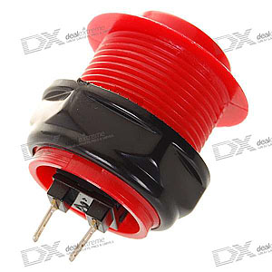


Check it out! Fits perfectly in the original button assembly! All I had to do is drill two holes on each side of the cabinet. One for the button, and one small hole for the wiring.

The button contacts are exposed of course, but I don't particularly think they are much of an eye sore. I was contemplating making a covering for them but for right now, not a priority. The left button (seen above) takes a little room away from the cardboard apron and pushes it down just a little, but not enough to look terrible.
The result? I can't even begin to tell you what a difference these buttons made! The originally weak and unresponsive flippers seem to have taken on new life and send the ball all over the play field with ease. They are also wonderfully responsive now. Dare I say I could probably now make trick shots with a little practice. This was probably the most dramatic and effective mods to this machine. I'd probably go out on a limb and say that nearly every single case of people experiencing bad flipper control on these machines can be chalked up to the horrid original button assemblies. They are literally garbage.
At this point I can come to a pretty definitive conclusion. In response to all the haters, I can understand their frustration. When you buy something you shouldn't expect to have to do some work on it to make it useable. On the other hand, I can't go so far as to dismiss Zizzle's pinball machines as absolute garbage, as I've noticed so many people calling them. Many feel putting any time into these is a waste of time and that paying any more than $50 for one (ouch!) is throwing money away. I wholeheartedly and sincerely beg to differ! It's a great little machine, though hindered with inherent design flaws that are easily fixed. Also, many fail to keep their expectations at a reasonable level. This is first and foremost a toy, plain and simple. Once should never expect these machines to perform at a level that even holds a candle to a multi-thousand-dollar commercial unit. For a toy, and for the price, it's impressive on all fronts.
For those who want a good pinball machine on the cheap out of the box... you're out of luck. But if you're willing to get your hands dirty and do a few simple (and let me emphasize cheap) modifications, and don't forget that it's a toy, you'll be happy. I can't speak on the fact that some of these were known to simply die after a few plays. This may be true on some faulty samples. In my case, I've played mine for hours at a time... my wife can tell you, with no problems whatsoever. Hopefully it'll stay that way.
I hope so far this blog has inspired anyone who's on the fence, or currently own a Zizzle pinball machine who wish to improve on its performance.
Now... onto the cosmetics....
Greetings landronartifacts,
ReplyDeleteWhere in the Chinese site called 'Deal Extreme' (dx.com) are the flipper buttons you used located? I couldn't find them anywhere.
Thank you very much!
Best regards,
W.H.
Look for; Arcade Button. Specifically the item is referred to on the site as; Repair Parts Replacement OBSF Button for Arcade Machine (Color Assorted)
ReplyDeleteThanks for creating this blog. My dad gave me a marvel super heroes zizzle a few weeks back. I think it is a "2nd gen" zizzle (back lights up and the background is darker). My kids and I enjoyed it at first, but the flaws of the machine drove me to the point that I was going to trash it. Your blog inspired me to mod it.
ReplyDeleteI wanted to share my experience with the flippers for the benefit of others. The right flipper was terribly weak and could never drive the ball up them left ramp. I did purchase arcade buttons, but I haven't installed them yet (they are being shipped as I write this).
I also notice that the power supply I had was a 20 Volt DC, 2.5 Amp output (manufacturer=Hitek). This machine was at least third hand so I'm not sure if it was the original power supply. The zizzle says it is a 24 V DC input with 60 W so I was suspicious that the power supply was a problem. I purchased a Universal laptop power supply off Amazon (Up to 24 V DC output, 90 W max) and installed it. The difference was enormous. I can easily go up the left ramp now. In fact the flipper has so much power that the hardest shot is to get it to go up the left ramp drop in the hole that is half way across. I only have about 30 minutes of play time with the new power supply, but it seems like the new power supply solved my problem.
Here are some other observations that may be useful to others:
-The circuit that goes from the mother board to the button and back is a 5 volt circuit. This circuit is just telling the motherboard when to send power to the solenoid (and when to make the redundant flipper sound effect).
-The nominal power to the solenoid is 24 V DC (I suspect it is just outputting the voltage that comes into the machine because it was 20 V DC when I was using my old power supply). That is, if you disconnect the solenoid the voltage that is produced by the mother board to send to the flipper is 24 V DC. I was surprised by this because on another forum a guy took pictures of a disassembled flipper and the solenoid appears to say it is rated for 12 V DC (http://www.pinballnirvana.com/forums/showthread.php?t=5847&page=2). Interestingly, under load the voltage drops substantially. That is, when the solenoid is in the circuit the steady state voltage across the solenoid when the button is held is 6.6 VDC or so (was around 5.5 volts with my old power supply). My suspicion is that there is substantial internal resistance in series with the solenoid so that the voltage drops when the current flows. Another possibility is that the power supply needs substantially more power to keep the voltage up while supplying current.
-There is a suggestion on several other boards to disconnect the control circuit (5 volt one) and plug directly in to the power coming in to the machine through the button. DO NOT DO THIS UNLESS YOU UPGRADE YOUR BUTTONS. Most importantly, the cheap momentary switches will quickly die in this configuration (not sure if it is the voltage or the current that killed mine, but the button on the side I tested totally died). Secondly, the flipper is already getting 24 volts nominally. That said, it is possible that there may be less internal resistance by hooking up directly through the power coming in to the machine. The page I linked above is the origin of the recommendation to disconnect the 5 volt circuit. The guy actually recants a post or two latter, but that didn't stop a bunch of people from copy pasting his suggestion all over the web. I wonder how many zizzles have ended up in the trash this way.
Thanks again for this blog. I will add another comment if anything interesting comes from installing the new buttons.
I have a POTC in need of repair. I could not find a schematic, and phone disconnected at Zizzle. Need to get a pic or two of wiring. Looking to locate where the black and red wires coming off the rocker power switch connect. Also, need to verify where the second connector from the rear on the edge of the main board connects to. Thanks and would appreciate the help. RRRichmond@gmail.com
DeleteI'm afraid I can't help you there, and Zizzle has been defunct for some years now. I'm not familiar with how the inner electronics work as I'm not an electrician. If your unit doesn't power on you might have a bad power adapter or something else fried inside. I did take a quick look at the main board and it does have a small fuse. Perhaps that's blown out?
DeleteThe resistance you describe in the solenoid is most likely caused by the ceramic resistors that are hooked up in series with the solenoids. I believe these are there to keep them from overheating and blowing out. You'll notice the resistors get really hot when you hold the flipper up for an extended time. In a real pin machine, the solenoid gets a full dose of voltage for the initial pull, simultaneously an internal switch cuts the power down to a minimum, just enough to keep the flippers in an up position while holding the weight of the ball. I think the ceramic resistors are performing a similar function here, though in a more sloppy sense. After all, this IS a toy after all.
ReplyDeleteAnd buddy, you look like you know what your doing far more than I do with the internal electronics. But I gotta say in all honesty, all of the flipper response and weakness problems were solved with simply changing the buttons as the original ones were useless. Rewiring in the insides to get more power to the flippers is probably more trouble than it's worth. Keep in mind it's a fragile plastic play field, and a small one at that so you don't really need much ball speed to play it.
Ok that makes sense about the resistors and the how it is simulating a similar function in a real pin. That may also explains why I see the voltage across the solenoid jump to 8-10 Volts before settling in to a steady state value of around 6 volts. Perhaps the zizzle is trying to do the same thing as a "real" pin. When I open up the machine to install the new buttons I'll check that out.
DeleteOut of curiosity, does your machine also have the two separate circuits (one to power the solenoid and one to send a signal from the button to the motherboard)? Also, what are the ratings listed on your AC/DC converter? I'm assuming the machines are suppose to come with a 24 V DC output and the 20 V DC supply I had was something a previous owner had laying around.
where can i get the buttons??
DeleteWow Nice post, thanks for sharing. The best way to purchase pinball machines is to be sure you are working with industry experts that thoroughly go over the entire machine prior to delivering the pinball machine to your home or business. Buying on an auction website can be risky as you never know for sure just who you are dealing with. A good source for pinball machines is monkeys arcades.Best Lighted Pinball Speakers
ReplyDeletein web I can get the buttons?
ReplyDelete